Friday, October 24, 2014

Need for Modulation


1) To reduce Antenna height

The antenna height required to transmit a signal is proportional to operating wavelength. For efficient transmission, the minimum antenna height required should be lambda/4. So if we want to transmit a low frequency signal(f), we have v=f*lambda. lambda is inversely proportional to frequency, so low frequency means large wavelength(lambda)--> Antenna required will be very high. Modulation converts the given signal to high frequency signal.

2) To reduce noise

The effect of noise will be more at some frequencies and the effect will be less at some other frequencies. Modulation shifts the spectrum to other band of frequencies where noise effect will be less.

3) Conversion of bandlimited signal to narrowband signal

 Modulation converts a bandlimited signal to a narrowband signal that has ratio between highest frequency to lowest frequency less, so that we can transmit a signal with single antenna which wouldn.'t be possible if the ratio was high.(Which is the case if modulation is not performed on the respective signal)

4) Multiplexing

More than one signal can be transmitted through the same communication channel. By modulation it is possible. We will see about it in detail in the coming posts.
\


Wednesday, October 22, 2014

Transient analysis of RLC/RL/RC circuit- PSPICE Simulation

In this post, we will see the transient analysis of RL circuit with the help of an example. Before solving that we should understand the behaviour of Inductor in the steady state condition. To know in detail. See this video--> Prerequisite

Let's take the following example

 PSPICE simulation of RLC circuit
Main diagram


A) Before t=0-

In the above example, before t=0-, i.e in a steady state condition, inductor will act as a short circuit, so the current through the inductor at t=0- will be 0.75A. i(t), in this case will be 0.

B) At t=0+

After the switch S is closed, the inductor will resist the change, so it will not permit this to happen. Even after the switch is closed at t=0. At t=0+(Just after the switch is closed), inductor will still take 0.75A. So the two resistors which are in parallel divide the remaining 0.75A among themselves. i.e i(t)=0.375A at t=0+.


c) t=0+ to infinity

The inductor is a memory element, so it resists the change in current. It takes certain time to reach a steady state. At steady state(t=infinity), the current through il=0.5A(Since L acts a short circuit, the above circuit will be just  a parallel combination of 3 resistors each of 10 ohm. i(t) |t=infinity=0.5A.

General expression of i(t) can be found using the following equation(Refer main diagram to know which is i(t))

i(t)=Final value+(Initial Value-Final value) exp(-t/tc)  ,where tc=time constant of a circuit.

so, 
i(t)=0.5+(0.375-0.5) exp(-1000t) A.

i(t)=0.5-0.125*exp(-1000t) A.

At t=0, i(t)=0.375A
At t=infinity, i(t)=0.5A


                                              PSPICE SIMULATION


i(t)

iL

Red color=i(t). Green color=iL


Note

Because of the presence of inductor, the current i(t) takes certain time(5 time constant) to reach its final value of 0.5A. The current i(t) value varies from 0.375A to 0.5A .
Inductor resists the change in the current.


Simulation video--> Part 1 and Part 2

Saturday, October 11, 2014

Control System Quiz

1) The transfer system of the system which will have more steady error for unit step input is
a) 80/(s+1)(s+2)(s+3)
b)120/s(s+1)(s+15)
c) 60/(s+0.5) (s+3)(s+5.5)
d)120/(s+1)(s+4)(s+15)
Show/hide solution

2)When the gain 'K' of the system is increased, the steady state error of the system
a)Increases
b) Decreases
c) Remains unchanged
d) May Increase or decrease
Show/hide solution

3)A unity feedback system has forward path transfer function G(s)=K/s(s+2). If the design specification is that the steady state error due to ramp input is 0.05,the value of K allowed is
a)20
b)40
c)10
d)80
Show/hide solution

Friday, August 15, 2014

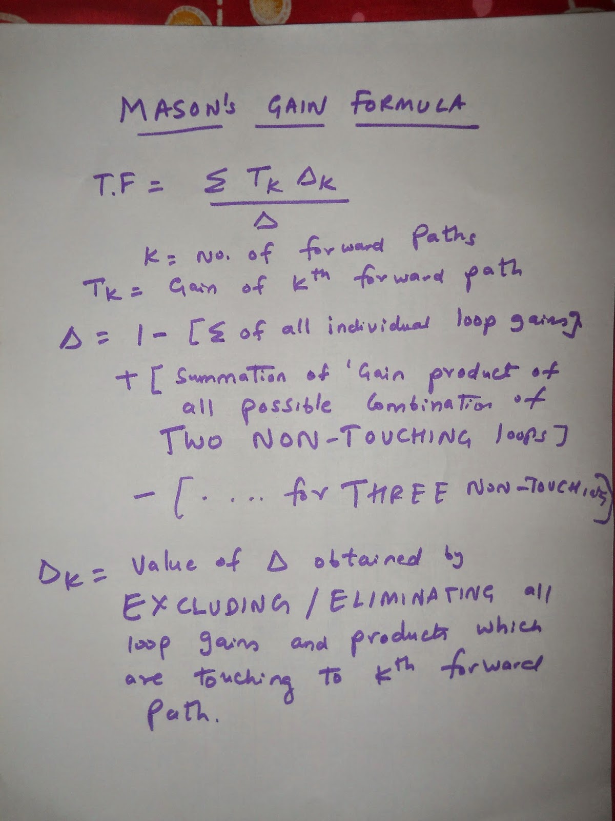
Mason's gain formula example

Control Systems is a fantastic subject and I wanted to write some topics regarding that. The first thing you notice in control system class is to find the gain of a "PRETTY BIG BLOCK" by using various reductions techniques. The steps involved will be :
1) Multiply the gain(G) of the blocks which are in series and add the gains(G) which are in parallel
2) Switch the take-off point to the right side of the block and blah-blah stuff. 

So, in order to avoid all these steps, one brilliant lad, invented a formula, which is named after him(We are accustomed to FORMULA, isn't it? ). That formula makes life easy for us who study control system. That formula is called, MASON'S GAIN FORMULA. Mason's gain formula applies only to LINEAR SYSTEMS.

If you don't know what Linear System is? Google has a quick ans : A general deterministic system can be described by operator, H, that maps an input, x(t), as a function of t to an output, y(t), a type of black box description. Linear systems satisfy the properties of superposition and scaling or homogeneity.


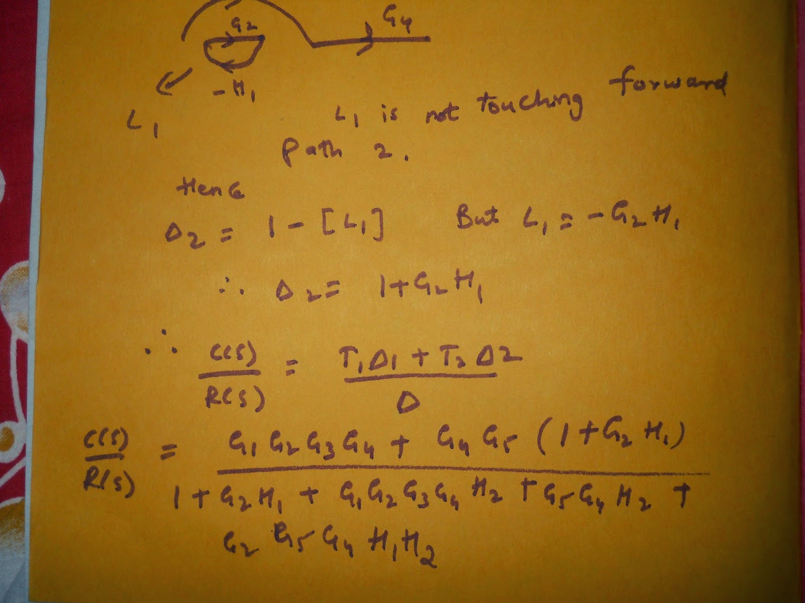
Mason's gain formula Example.

I have solved  a Signal Flow graph using Mason's gain formula. The explanation would be suffice I guess. Kindly go through the snapshots and revert back for any doubts.
Tip:Zoom the pic for better clarity

Mason gain formula example


Monday, August 11, 2014

The Walking man on a LCD using 8051 microcontroller. Trailer


This is a video on "The walking man on a LCD" which has been done using 8051 Microcontroller. We would like to know if anybody is interested in making this project. ? If yes, we will make a tutorial or two on  "How to make a walking man on 16*2 LCD using 8051 Microcontroller"? .