
No circuit element has contributed to the " STABILITY of ANALOG CIRCUIT" as much as Emitter degeneration resistors. Especially when you are dealing with BJT, a lot of factors decide the working of the circuit such as Beta value of transistor, temperature etc. If circuit characteristics change w.r.t any of the temperature, beta etc cannot be considered as a stable circuit.

This is the popular current mirror circuit with 2 EMITTER DEGENERATION RESISTORS R1 and R2.
As you can see. VB1=VB2( The base of two BJT's are connected to each other).
The Red Probe will show the current of Q1 transistor in simulation. Let's call the collector current of Q1 as I1
The Green Probe will show the current of Q2 transistor in simulation . Let's call the collector current of Q2 as I2.
*Neglecting base current*
Assuming both BJT's are fabricated at a same time under same conditions(Which isn't the case practically, so there will be a slight error in calculation). Let's assume VBE1=VBE2
In the below circuit. R1=8k and R2=1k, So I2 should be 8 times I1 and you can see that I2 is 8 times I1.


Then what has to be done to make circuit independent of all those external factors?
Soln: Most of the time, Emitter degeneration resistor acts as a savior. In this post, we will see how emitter degeneration resistor(s) decide the overall working pattern of a current mirror.
Here is a sample circuit
This is the popular current mirror circuit with 2 EMITTER DEGENERATION RESISTORS R1 and R2.
As you can see. VB1=VB2( The base of two BJT's are connected to each other).
The Red Probe will show the current of Q1 transistor in simulation. Let's call the collector current of Q1 as I1
The Green Probe will show the current of Q2 transistor in simulation . Let's call the collector current of Q2 as I2.
*Neglecting base current*
By using Simple KVL,
VB1=VB2
VBE1+I1*R1=VBE2+I2*R2
Assuming both BJT's are fabricated at a same time under same conditions(Which isn't the case practically, so there will be a slight error in calculation). Let's assume VBE1=VBE2
In that case, I1*R1=I2*R2
I1/I2=R2/R1.
I2= I1*(R1/R2).
Since we are dealing with BJT's calculating current is little tedious, so lets concentrate on ratios of two currents I1 and I2 as shown by Red and green probe respectively.
In the above circuit, R1=5k and R2=1k. So , I2=5*I1. which you can see below. The mirrored current totally depends on emitter degeneration resistor and doesn't change with the Beta value of BJT or the temperature.
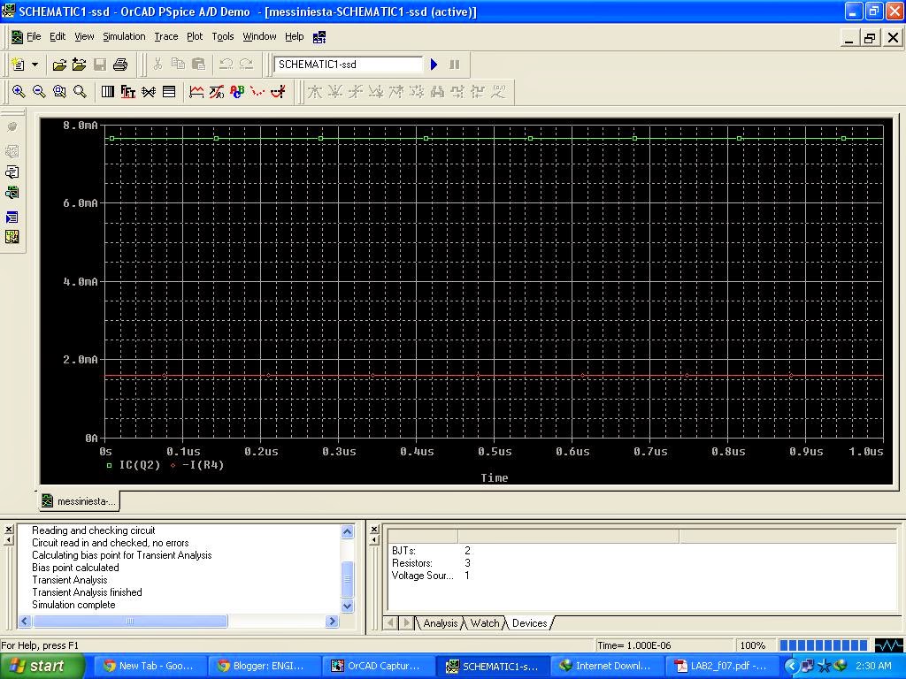 |
| I2=7.6mA and I1=1.6mA. I2 is 5 times(Almost) |
In the below circuit. R1=8k and R2=1k, So I2 should be 8 times I1 and you can see that I2 is 8 times I1.
In this post, we demonstrated the simple effect of emitter degeneration resistor. For any doubts, contact us via comment box or the email id.