
Buck converter or DC to DC step down converter is a switched mode power supply (They have maximum efficiency unlike linear regulators ) Boost converter is also similar as discussed earlier.
REFER BOOST CONVERTER -> BOOST converter

It consists of two switches as shown above - One switch and a Diode(Which acts a switch)
Cases: Switch!! on and off state


REFER BOOST CONVERTER -> BOOST converter
It consists of two switches as shown above - One switch and a Diode(Which acts a switch)
Cases: Switch!! on and off state
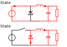
A buck converter operates in continuous mode if the current through the inductor (IL) never falls to zero during the commutation cycle. In this mode, the operating principle is described by the plots in figure
- When the switch pictured above is closed (On-state, top of figure 2), the voltage across the inductor is
 . The current through the inductor rises linearly. As the diode is reverse-biased by the voltage source V, no current flows through it;
 - When the switch is opened (off state, bottom of figure 2), the diode is forward biased. The voltage across the inductor is
 (neglecting diode drop). Current IL decreases.
The energy stored in inductor L is

Therefore, it can be seen that the energy stored in L increases during On-time (as IL increases) and then decreases during the Off-state. L is used to transfer energy from the input to the output of the converter.
The rate of change of IL can be calculated from:

With VL equal to  during the On-state and to
  during the Off-state. Therefore, the increase in current during the On-state is given by:
during the On-state and to during the Off-state. Therefore, the increase in current during the On-state is given by:
Conversely, the decrease in current during the Off-state is given by:

If we assume that the converter operates in steady state, the energy stored in each component at the end of a commutation cycle T is equal to that at the beginning of the cycle. That means that the current IL is the same at t=0 and at t=T (see figure 4).
So we can write from the above equations:

It is worth noting that the above integrations can be done graphically: In figure 4,  is proportional to the area of the yellow surface, and
  to the area of the orange surface, as these surfaces are defined by the inductor voltage (red) curve. As these surfaces are simple rectangles, their areas can be found easily:
  for the yellow rectangle and
  for the orange one. For steady state operation, these areas must be equal.
is proportional to the area of the yellow surface, and to the area of the orange surface, as these surfaces are defined by the inductor voltage (red) curve. As these surfaces are simple rectangles, their areas can be found easily: for the yellow rectangle and for the orange one. For steady state operation, these areas must be equal.
As can be seen on figure 4,  and
and  . Where D is a scalar called the duty cycle with a value between 0 and 1. This yields:
and . Where D is a scalar called the duty cycle with a value between 0 and 1. This yields: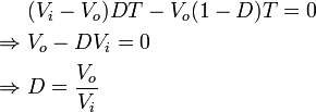
From this equation, it can be seen that the output voltage of the converter varies linearly with the duty cycle for a given input voltage. As the duty cycle D is equal to the ratio between tOn and the period T, it cannot be more than Therefore,  . This is why this converter is referred to as step-down converter./
. This is why this converter is referred to as step-down converter./
There is also a Discontinous mode which is tricky lets leave that part. And for now, Just know that. Vo can be changed by changing the duty cycle.
Lets get a vout=6v from 12v input with maximum efficiency (95% and above)
PSPICE simulation of BUCK converter
Calculation part :
IRF 150 is the POWER MOSFET . We should use Power MOSFET in switch mode power supply.
Note:Connect Vpulse negative terminal to MOSFET source.
Vi=12v.
we need vo=6v. so set duty cycle D=1/2.In order to do that.
Choose Vpulse in PSPICE and assign values as shown in .
PW(ton)=1.25u
Period(T)=2.5u (frequency =1/T)
So D(Duty cycle) = 1.25u /2.5u
where ton=DT, T=2.5u-->> f=1/T=400khz
Diode D1N4000 is fine.
Important part is calculation of L and C values for BUCK converter.
R which is parallel to capacitor is Load resistor. And Please note the output voltage changes if load changes as it is open loop configuration and not closed loop.
In closed loop you will have constant output voltage independent of load changes.which i will discuss in another post
Choose capacitor value as few microfarads.
No comments:
Post a Comment