
Current Mirror is the important invention in the field of analog electronics.In the design of IC's i.e Integrated circuits. CUrrent Mirrors are extensively used for biasing various analog circuits.
From Differential amplifiers to Voltage references Like Band gap references. All need current mirror for biasing.
Current Mirror


From Differential amplifiers to Voltage references Like Band gap references. All need current mirror for biasing.
Current Mirror

This is the basic current Mirror circuit. It consists of the following
1)Diode connected MOS M3
2)A mosfer M1 whose gate is connected to gate of M3
3)A 1k ohm R1 resistor is used to define a reference current
4)A 100 ohm (R2) is used) to get mirrored current
Working: Since both mos M1,M3 have common ground and both gates are shorted. Vgs3=Vgs1
we know that
Id(SATURATION)=un.Cox.(W/2L) {(Vgs-vth)*(vgs-vth)}
since Vgs of both MOS are equal and maintaining other parameters equal.
Iout=Iref
Important point : 1) Keeping Both MOS in saturation is important
M3 is a diode connected mos. i,e since gate is shorted to drain
Vds=vgs. condition for saturation is vds>=vgs-vth.
This condition is always satisfied in M3
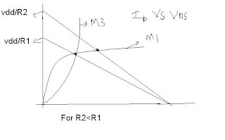
2) now The main design criteria is keeping M1 in saturation.
This is possible only if R2<R1

see the flat portion in the curve.SO Iout=Iref(Almost)
If R2>R1 .The mosfet M1 goes into triode region

For R2>R1 . Iout will be very less than Iref because M1 enters triode region.
So to design a current mirror.Choose R2<R1. You ll get almost accurate current mirror
FOr R2=100 ohm
output :

FOR R2=3k
See down!


For R2=3k. It VIOLATES THE RULE of R2<R1.
So M1 enters triode region.So the output current and reference current are differed heavily as shown above.
Red marker=Reference current
Green Marker=output current
Thank you
Like the facebook page and subscribe