Friday, September 12, 2014
Friday, August 15, 2014
Mason's gain formula example
Control Systems is a fantastic subject and I wanted to write some topics regarding that. The first thing you notice in control system class is to find the gain of a "PRETTY BIG BLOCK" by using various reductions techniques. The steps involved will be :
1) Multiply the gain(G) of the blocks which are in series and add the gains(G) which are in parallel
2) Switch the take-off point to the right side of the block and blah-blah stuff.
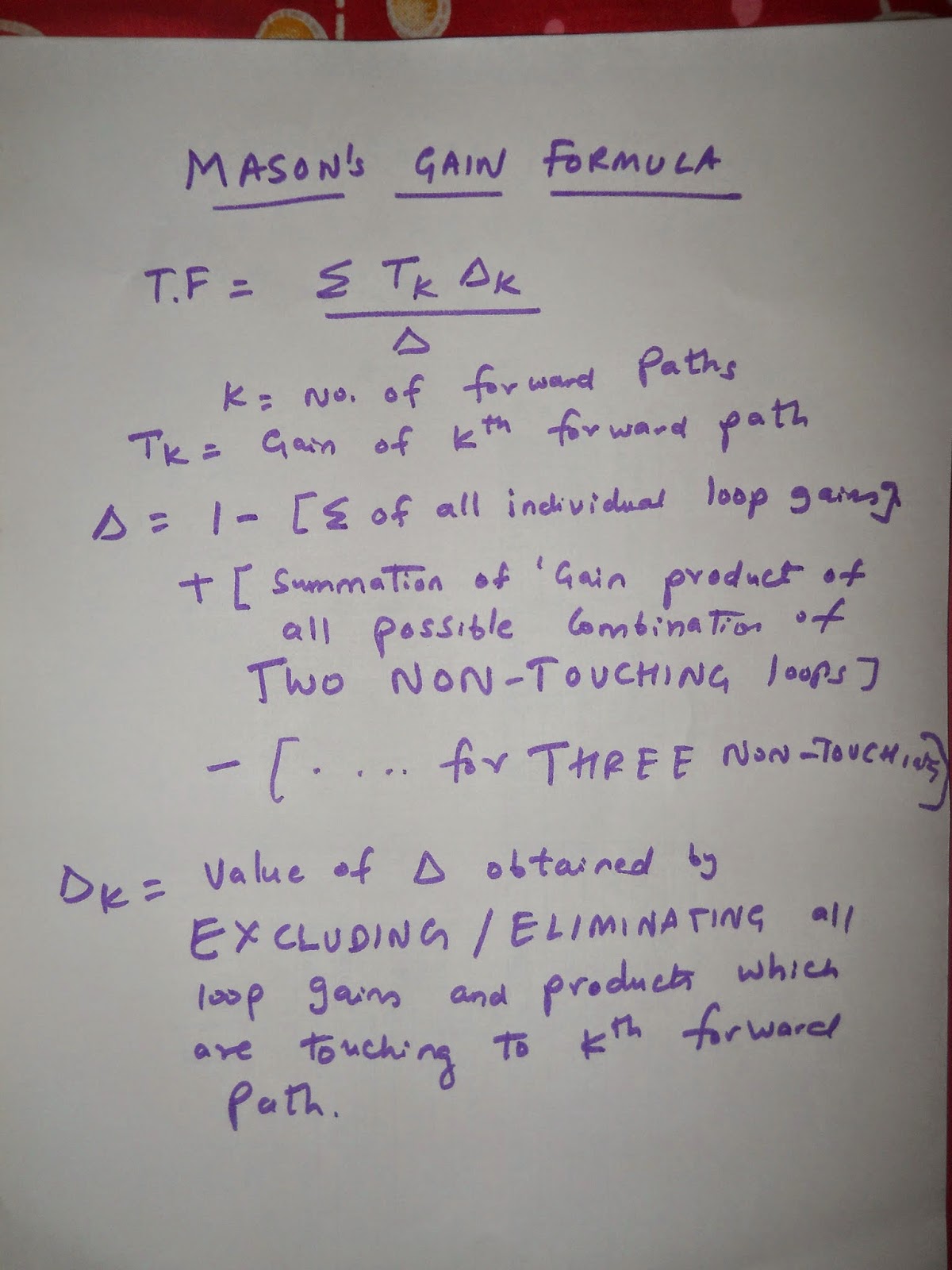
So, in order to avoid all these steps, one brilliant lad, invented a formula, which is named after him(We are accustomed to FORMULA, isn't it? ). That formula makes life easy for us who study control system. That formula is called, MASON'S GAIN FORMULA. Mason's gain formula applies only to LINEAR SYSTEMS.
If you don't know what Linear System is? Google has a quick ans : A general deterministic system can be described by operator,  , that maps an input,
  , as a function of
  to an output,
  , a type of black box description. Linear systems satisfy the properties of superposition and scaling or homogeneity.
Mason's gain formula Example.
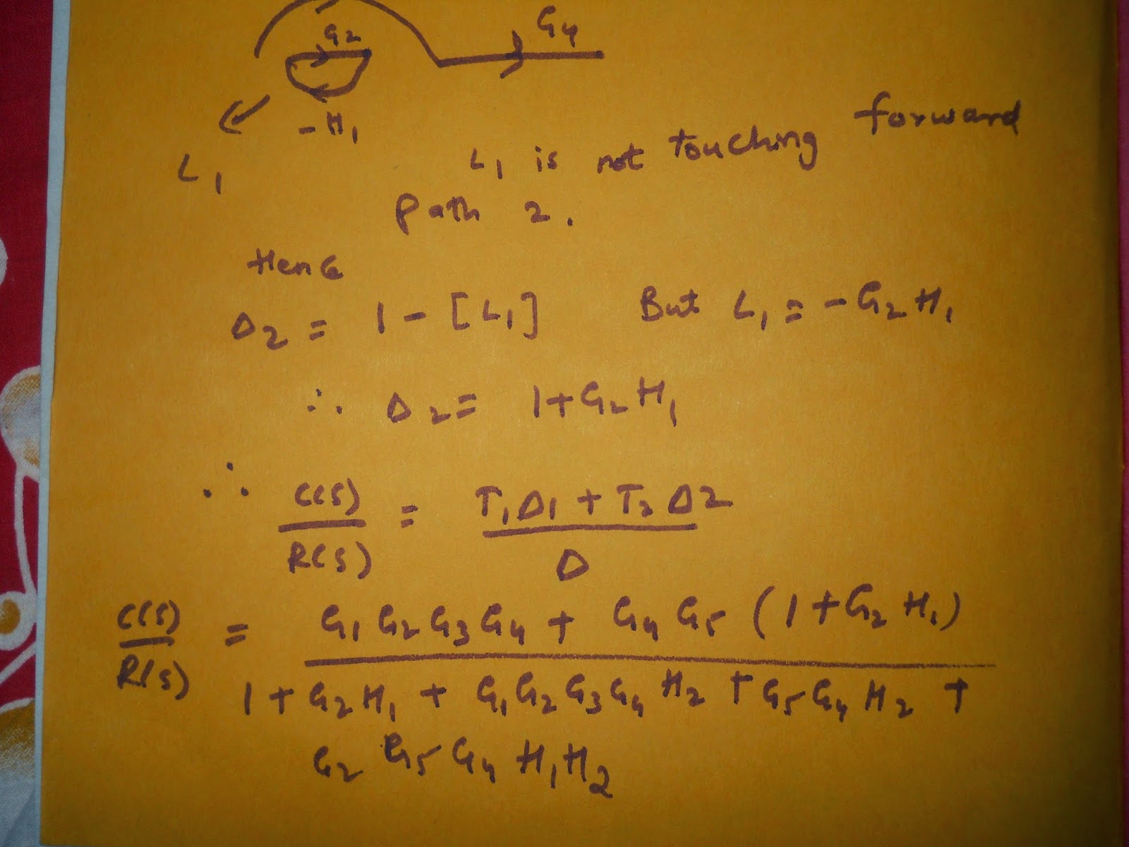
I have solved a Signal Flow graph using Mason's gain formula. The explanation would be suffice I guess. Kindly go through the snapshots and revert back for any doubts.
Tip:Zoom the pic for better clarity
Monday, August 11, 2014
Wednesday, July 23, 2014
How to print data on second line of 16*2 LCD using Microcontroller (8051)
Let us see how to print on the second line of 16*2 using 8051.
Prerequisite: Knowledge about lcdcmd() and lcddata() functions.
Circuit diagram.
Here is the DDRAM address of 16*2 LCD
For 16*2 LCD
ROW1 : 0x80 0x81 0x82 0x83 0x84 ...... 0x8F
ROW2 : 0XC0 0XC1 0XC2 0XC3 0xC4......0xCF
The Display data RAM is the set of addresses where the cursor moves. The data will be written on the position where cursor is. The cursor position(address) can be changed by sending various commands to LCD. For ex: lcdcmd(0x80+02) means Cursor points to 1st row, 3rd column.
Suppose the data is "welcome". On executing 0x82 command,the cursor points to the 1st row, 3rd column. If we start sending data to the LCD. 'w' will be printed on the third position. By default, the address will be incremented for new alphabet. Hence 'welcome' will occupy 03 to 09 address in the above figure.
To use second row, first column of the 16*2 LCD. We should point the cursor to that position. This can be done by using lcdcmd(0x80+0x40) .To use second row, second column(0x80+0x41) and so on. After pointing the cursor to that position. We can write the respective data using lcddata() function.
Using these basic commands, we can print the data on second line of 16*2 LCD.
Many animations can be done by playing with the addresses of DDRAM. Here is a simple demonstration!
Here in the second row, we started printing values from (0x80+0x4D) address and decremented the initial address till the whole array is print. If anyone needs the code and simulation, please use the comment box :).
Saturday, July 19, 2014
Create a frequency using 8051 Microcontroller. Timer 0 Mode 1. Proteus simulation
8051 has two timers. Timers can be used to generate delay. So, we can create pulse of various frequencies using 8051. Let's see as how to create a frequency on particular pin of microcontroller, 8051. We will use proteus simulation to demonstrate the same.
Circuit diagram
Here is the code, which generates a frequency of 10Hz on pin P2.7.
Code :
Circuit diagram
Here is the code, which generates a frequency of 10Hz on pin P2.7.
Code :
#include "reg52.h"
#define Baud_rate 0xFD  // BAUD RATE 9600
void delay(void);
sbit App = P2^7;


void main()
{
while(1)
 {
 App=~App; //To generate a pulse(ON/OFF)
 delay();
 }
}

void delay(void)
{
  TMOD=0x01;      //Timer 0 mode 1
  TL0=0xFD;
  TR0=0x4B;
  TR1=1;         //start timer
  while(TF1==0); //Timer flag
  TR1=0;         //reset timer
  TF1=0;
}
The Microcontroller used here has a crystal frequency of 11.0592MHz.
In order to generate a Frequency of 10Hz, we need to use timer registers.
The steps to load values into TH and TL registers which generate delay are as follows
1) Divide the desired time delay by 1.085us. Here delay is 1/10=100ms. So, 100ms/2=50ms/1.085us=46083
2) Perform 65536-delay=65536-46083=19453
3)Convert the value obtained in the above step to Hex. 19453 is in decimal, in Hex, the value is 4BFD.
4)Load TH=4B
5)Load TL=FD
when you start the timer, the timer registers will count till FFFF generating the desired delay. Thus generating a pulse of required frequency/delay.
Friday, July 18, 2014
Send data from 8051 to Hyperterminal (PC/Computer)
My first post here was http://www.hobbyprojects.in/2013/03/serial-communication-between-pc-and-8051.html which went viral. I had also made a video on sending data from 8051 to Hyperterminal(which will be present in PC). The video was missing in the website. We will see in detail , the serial communication between Microcontroller and Hyperterminal.
How to send data from Microcontroler to Hyperterminal ?
Make the port of COMPIM as COM4. The data sent from Microcontroller will flow via COM4.
Since, the Hyperterminal doesn't have many ports inbuilt, we will use virtual ports emulator to get the ports. Here we have connected COM2 and COM4 in pair. The data sent from COM4 will also flow through COM2 as they are connected.
Hyperterminal will be in the following in the computer. Start->All programs--> Accessories-->Communications-->Hyperterminal
Here the port via which the hyperterminal makes communication with microcontroller is COM2.
The actual data, "Hello" which is transferred from Microcontroller (8051) to PC/Computer will be displayed in the hyperterminal. Thus, the data is successfully transmitted from 8051 to Hyperterminal.
How to send data from Microcontroler to Hyperterminal ?
 |
| Detailed Circuit diagram |
The circuit consists of Microcontroller, Max232, COMPIM, inverters and virtual terminal as shown in the figure. We have used Free virtual serial ports emulator so that we can connect two or three communication ports together.
 |
Hyperterminal will be in the following in the computer. Start->All programs--> Accessories-->Communications-->Hyperterminal
Here the port via which the hyperterminal makes communication with microcontroller is COM2.
 |
| Set the properties. Baud Rate should be as defined in 8051 |
 |
| Click on Echo typed characters locally |
The data sent from Microcontroller will be displayed on Hyperterminal. Start the simulation, you can see the output in virtual terminal as shown below.
 |
I have made a video too. Please watch here. The code is simple, if anyone needs the code. Please use the comment box. Thanks.
Saturday, June 14, 2014
Current Mirror with Emitter degeneration resistors
No circuit element has contributed to the " STABILITY of ANALOG CIRCUIT" as much as Emitter degeneration resistors. Especially when you are dealing with BJT, a lot of factors decide the working of the circuit such as Beta value of transistor, temperature etc. If circuit characteristics change w.r.t any of the temperature, beta etc cannot be considered as a stable circuit.
This is the popular current mirror circuit with 2 EMITTER DEGENERATION RESISTORS R1 and R2.
As you can see. VB1=VB2( The base of two BJT's are connected to each other).
The Red Probe will show the current of Q1 transistor in simulation. Let's call the collector current of Q1 as I1
The Green Probe will show the current of Q2 transistor in simulation . Let's call the collector current of Q2 as I2.
*Neglecting base current*
Assuming both BJT's are fabricated at a same time under same conditions(Which isn't the case practically, so there will be a slight error in calculation). Let's assume VBE1=VBE2
In the below circuit. R1=8k and R2=1k, So I2 should be 8 times I1 and you can see that I2 is 8 times I1.
Then what has to be done to make circuit independent of all those external factors?
Soln: Most of the time, Emitter degeneration resistor acts as a savior. In this post, we will see how emitter degeneration resistor(s) decide the overall working pattern of a current mirror.
Here is a sample circuit
This is the popular current mirror circuit with 2 EMITTER DEGENERATION RESISTORS R1 and R2.
As you can see. VB1=VB2( The base of two BJT's are connected to each other).
The Red Probe will show the current of Q1 transistor in simulation. Let's call the collector current of Q1 as I1
The Green Probe will show the current of Q2 transistor in simulation . Let's call the collector current of Q2 as I2.
*Neglecting base current*
By using Simple KVL,
VB1=VB2
VBE1+I1*R1=VBE2+I2*R2
Assuming both BJT's are fabricated at a same time under same conditions(Which isn't the case practically, so there will be a slight error in calculation). Let's assume VBE1=VBE2
In that case, I1*R1=I2*R2
I1/I2=R2/R1.
I2= I1*(R1/R2).
Since we are dealing with BJT's calculating current is little tedious, so lets concentrate on ratios of two currents I1 and I2 as shown by Red and green probe respectively.
In the above circuit, R1=5k and R2=1k. So , I2=5*I1. which you can see below. The mirrored current totally depends on emitter degeneration resistor and doesn't change with the Beta value of BJT or the temperature.
 |
| I2=7.6mA and I1=1.6mA. I2 is 5 times(Almost) |
In the below circuit. R1=8k and R2=1k, So I2 should be 8 times I1 and you can see that I2 is 8 times I1.
In this post, we demonstrated the simple effect of emitter degeneration resistor. For any doubts, contact us via comment box or the email id.
Subscribe to:
Comments (Atom)


